 WebMail

Creating and using 3D solid tool in NX (part 1)
Very common request from NX CAM users is possibility to use 3D solid tool assemblies, which are provided by tool vendors. Here you will find answers how you can do it with NX.
Using 3D solid tool models is usually needed in case of turning tools, mostly because of complex shapes of holders. This is why I will start with turning tool example
It is very important to remember:
3D Solid tool assemblies are used only in Verification of a tool path and in ISV.
All tool paths are generated basing on parametric tool. This is why in this example I also create cutting insert as parametric tool.
Similar as in my previous posts, I will present it on a video
With this approach you will have to create some files and directories manually. Also you will have to switch to Machine Tool Builder module to create tool junctions.
Next week I will describe more automatic way, which will allow you to do it all without leaving NX CAM.
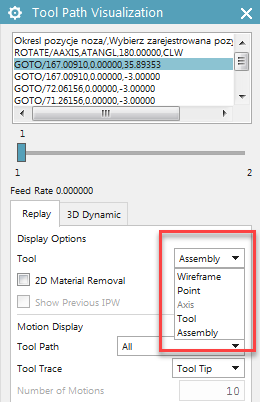
In NX verification you have an option to choose what you want to use – parametric tool, or 3D solid tool:
Out of the box directory for 3D tool models, is:
(…)\MACH\resource\library\tool\graphics
You can create entire tool model in one file and place it directly in this directory, but my best practice is to do it as I showed it on a movie:
– create folder with identical name as Library Reference of a tool in ascii library
– top assembly file should have identical name as Library Reference of a tool in ascii library
– save cutting and non-cutting portions of a tool in separate components.
This topic is continued in next week’s post.


Marek,
Thank you so much for the video, this is a new way to create graphics tool that I’ll need to learn.
Hi Omar,
New way? So which way you did it in the past?
Hi Marek,
I followed the steps on the PLM website video,
“https://community.plm.automation.siemens.com/t5/video/gallerypage/video-id/B5d2l5djotpwkgcnOdERIL2vO4q3Bk6V”
The graphic holder and insert were visible while creating the parametric insert on NX cam side, in your video you are creating the parametric insert in the cam side with the graphics holder/insert on the background, and going back to the cad side to take your measurements, other than that it’s the same method. One other difference, you picked an 80 degrees left hand OD tool if I remember correctly, then you picked 55 degrees insert, the insert came default on Tracking point P3!! From my short experience with NX turn I usually get P9 as default.
Thank you so much for you time, very informative video, I have learnt many tricks. “I’m new to NX, moved from Catia/Cimatron environment”
Looking forward to learn more from you, thanks again