 WebMail

Spindle Speed Attached to a Tool (Machining Data Library – part 1)
Have you ever wanted to have spindle speeds for each tool set automatically for CAM operations? Here you will find out how you can do it with NX CAM.
Method which I describe here, is the most simply use case for Machining Data Library in NX.
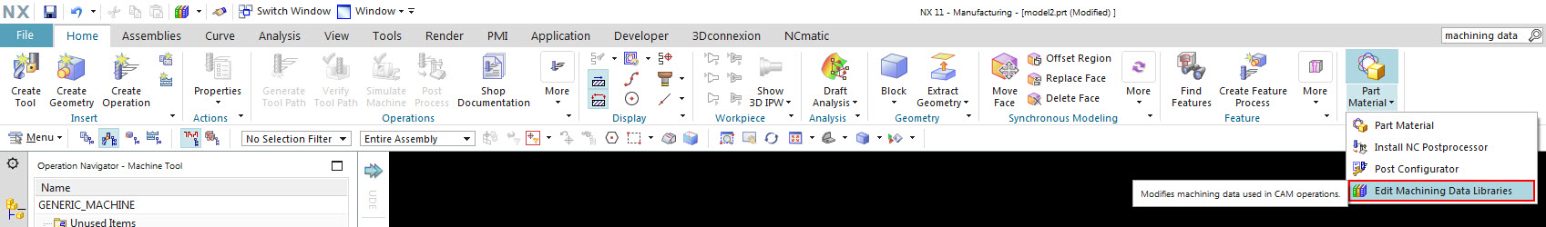
To edit Machining Data Library, go to Menu / Tools / Edit Machining Data Libraries. Or find this command in Home bar:
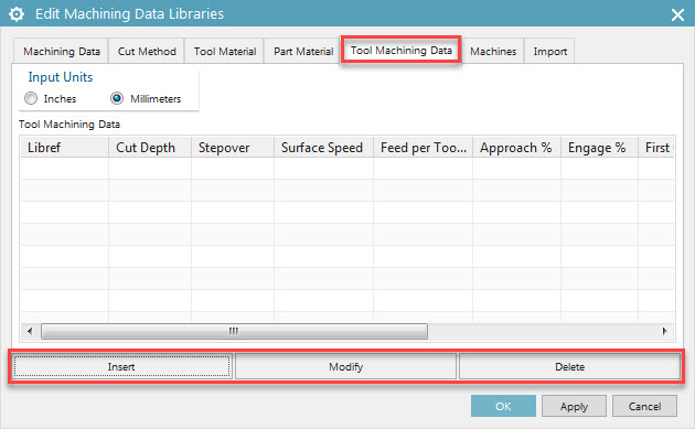
For our needs, this time we will use only Tool Machining Data tab of Machining Data Libraries dialog. To attach cutting parameters to a tool (which must be already defined in library), click Insert button and choose a tool from library.
With this approach, you can attach to every tool set of parameters:
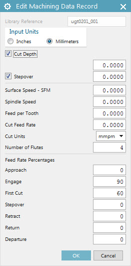
As we want to store only Spindle Speed and Feed Rates attached to each tool – we need to uncheck options for Cut Depth and Stepover. We would like to use those two options, when building more complex Machining Data Library (which I will mention later).
We can set Spindle Speed as rpm or SFM. No need to click calculator icon like in CAM operation dialog 😉
Feed Rates can be set as feed per tooth or feed per minute. Number of Flutes field displays parameter inherited from tool – I would use it only as information. I don’t see any reason of changing this value here, because number of flutes is already defined in tool.
Feed Rate Percentages allows us to set separate feed rates for different motion types. This works identical way as in CAM operation dialog. Value of “0” means:
– rapid for motion types recognized as non cutting motions
– 100% of Cut Feed Rate for motion types recognized as cutting motions.
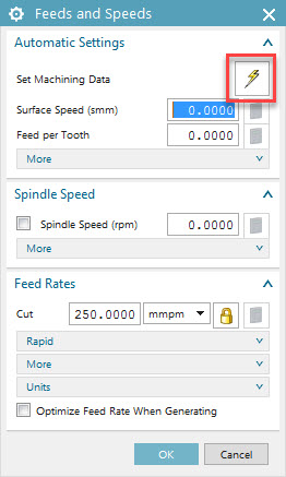
To apply this parameters in newly created CAM operation, simply click lightning icon in Feeds and Speeds dialog:
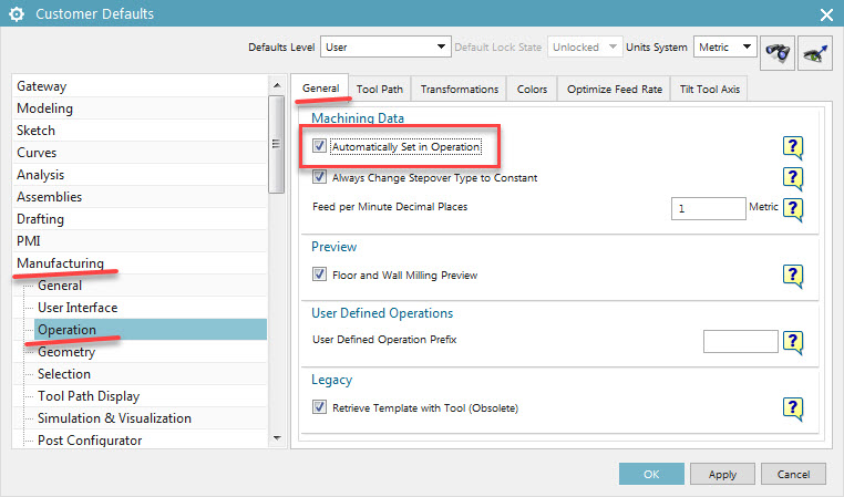
If you want to apply parameters from Machining Data Library automatically, without clicking lightning icon in every operation, set this option in Customer Defaults:
If I missed some step in my description here, you can also see how to do it on a movie:
As I mentioned, this is the simplest way of using Machining Data Library. In a more complex way we can build library of parameters considering all this parameters:
– tool diameter
– tool length
– material of the tool (or insert)
– machined material
– cut method (facing, slotting, roughing, HSM milling etc…)
Soon I will also describe full Machining Data Library. So stay tuned. You can find more content on my YouTube channel and my Facebook profile – and don’t forget to like it 🙂


Whats Taking place i am new to this, I stumbled upon this I have found It positively helpful and it has aided me out loads. I hope to contribute & assist other users like its helped me. Great job. bcdaefcaeefa