 WebMail

Cutter compensation output from NX CAM
Today I will discuss very fundamental topic, which is: using cutter compensation in NX.
In NX CAM (probably in every CAM actually) we usually don’t output entire NC program with cutter compensation turned on. It is used primarily for finish passes.
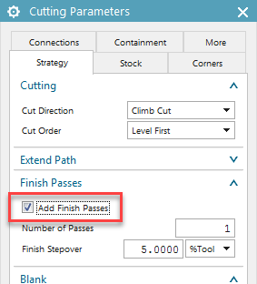
Keeping this in mind, for example in Cavity Mill operation, cutcom will be outputted only if we will turn on Add Finish Passes option:
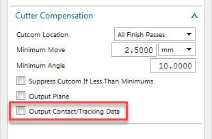
 To actually turn on the cutcom, we need to go to: Non Cutting Moves / More tab / Cutter Compensation, and choose if we want to turn it on only for final finish pass, or for all finish passes.
The most important setting is the last one. Output Contact/Tracking Data
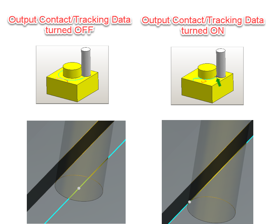
- With this option turned ON, we will get most “traditional” cutter compensation output. It means, that programmed coordinates applies to contact point of the cutter and geometry which it cuts. On CNC controller, operator sets real tool diameter in tool presets table. What controller does, is shifting cutter path for exactly half of real tool diameter.
- If we leave this option turned OFF, we will still get G41/G42 (or RR/RL) in NC code, but programmed coordinates will apply to center of cutter. On CNC controller, operator should not set real tool diameter in presets table, but only value of wear of the tool: difference between nominal tool and real/measured diameter. In this case controller shifts programmed cutter path only for the value of tool wear.
Below, you can see illustration of it. Note that in both cases cutcom is active, so G41/G42 (or RR/RL) will be outputted in NC code
In most cases user can decide which way he wants to use cutter compensation, but it is vital that machine tool operator should be aware which way was used…
From my experience, it is always easier for CAM software and for CNC controllers to use cutcom with Output Contact/Tracking Data turned off. But still most users prefer “traditional” method with coordinates applying to contact point of tool and geometry.
After activating cutcom, we have several options where we can specify details of how it should behave:
- Minimum Move – length of additional segment of the tool path which is required to activate cutter compensation mode (to move the tool from nominal path to compensated path. In practice, I usually set it to 55% of tool diameter, or leave it as zero.
- Minimum Angle – rotation angle of linear extension
- Suppress Cutcom If Less Than Minimums – if we turn this option on, cutcom won’t be activated if offset value will be less than Minimum Move and Minimum Angle
- Output Plane – Turn it on if you need information in which plane cutcom should be applied (XY, YZ, ZX). In most cases leave it turned off
There is also possibility to turn on cutcom using User Def Event “Cutter Compensation”, but it is not commonly used practice.


